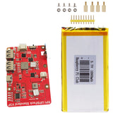
MakerFocus Raspberry Pi Expansion Board UPSPack Standard Power Supply -RPi V3P
If the product is show currently out of stock, meaning it is not regularly kept in inventory but is still available for purchase with a minimum order quantity. If you wish to place an order, please contact us directly for a quote.
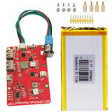
The new version of UPSPack V3 Plus (V3P) is applicable to the whole series of Raspberry Pi. Added EXT BTN interface to support PH2.0 4P self-locking switch with LED.
Generally speaking, users do not need to solder headers, and only need to connect the power cord to achieve uninterrupted power supply (the external power supply is disconnected, and the battery is uninterrupted power supply, which does not affect the operation of the Raspberry Pi). It is only needed when the GPIO power supply is needed soldering the 2P pin header, or use the Raspberry Pi serial port to communicate, and only solder the 3PIN pin header when developing new products. If you need to solder the headers, please test the basic functions when you receive the product before soldering the headers.
UPS board size: length 86.02mm x width 56.02mm x height 10mm (height: measured at the highest protruding position of the component, excluding battery height)
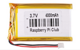
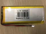
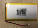
Be careful not to buy the wrong battery size, only 4000 mAh battery is smaller than the UPS motherboard, and other capacities are larger than UPS:
Model Volume (Length x Width x Thickness)
4000mAh 70mm x 41mm x 9.5mm
6500mAh 116mm x 50mm x 8mm
10000mAh 115mm x 65mm x 9mm
What's new on the Makerfocus RPi UPSPack V3 Plus?
|
Functional characteristics |
The RPi UPSPack V3 version |
The RPi UPSPack V3P version |
|
Enter the interface |
TYPE-C Interface (power cord compatible with new Pi4) |
TYPE-C Interface (power cord compatible with new Pi4) |
|
Output current |
5V 3A |
5V 3A |
|
External power failure, Pi continuous power supply (no restart) |
Support |
Support |
|
Hardware on and off switch |
YES |
YES |
|
GPIO power supply interface and UART, halt signal signal interface |
YES |
YES |
|
Lithium battery power statistics |
Support |
Support |
|
Turn on low pressure detection |
Support |
Support |
|
Abnormal detection of power adapter (power outage time detection) |
Support |
Support |
|
Detection of the output voltage value of the USB-A seat |
Support |
Support |
|
Automatic notify shutdown before battery depletion |
Support |
Support |
|
After the power failure, the program automatically |
Support (no manual intervention, program boot-up) |
Support (no manual intervention, program boot-up) |
|
After the outage switch, the UPS automatically switches to dormant mode |
Support |
Support |
|
The EXT BTN interface |
It is not supported |
Support for the PH2.0 4P self-lock switch button with LED |
|
Serial Port (UART) communication with Pi: |
|
|
|
Communication Settings |
9600 bps 8N1 |
9600 bps 8N1 |
|
Protocol version number |
V3.1(and later, Update) |
V3.2(and later, factory-latest) |
|
Agreement down-down compatibility |
Compatible with the older version of the V3 UPS communication protocol |
Compatible |
|
|
|
|
|
Single Bus Communications between UPS and Pi (System halt signal) |
|
|
|
Communication IO mouth |
UPS Motherboard STA Interface Connect Raspberry Pi GPIO18 (BCM 18) |
UPS Motherboard STA Interface Connect Raspberry Pi GPIO18 (BCM18) |
|
Communication protocol |
Pulse mode |
The level mode |
|
Software compatibility |
V3,v3P is more reliable with pulse detection (not compatible with V2 version of software) |
Method of level detection |
Performance parameter
The following are the UPS V3P output current, battery life, power failure without restarting, safe shutdown and automatic startup before the battery runs out, and several aspects to illustrate the performance and precautions of UPS V3.
1) Output current
Perform current test on UPS V3 V3P through EBC-A10H. The output current can reach: 5V 3A. After actual testing, when Pi4 runs the official Raspbian system, the normal power consumption is about 5V 1A. When peripherals such as a camera and U disk are inserted, the power consumption gradually increases to 5V 2A. Therefore, the use of UPS v3 to supply power to Pi4 has a large margin. And in the case of output 3A. The 2.54 pin header can also guarantee power supply above 5V. Users need to note that 5V and GND must use silica gel DuPont wires. If the ordinary DuPont line is used, when the current is large, it will cause a large line loss, so that the low voltage symbol of lightning can be observed on the Pi4 screen.

2) Battery life
UPS V3 V3P onboard battery interface is PH 2.0 package (compatible with old UPS motherboards), and the positive and negative signs are printed on the PCB board. The product provides 3 kinds of batteries with different capacities for customers to choose from. Customers can also plug in lithium polymer batteries with different capacities and rated voltages of 3.7V, or 3.7V 18650/21700/21650 battery packs. Note: The voltage range of the input UPS battery interface must be less than or equal to 4.2V. (All battery packs must be connected in parallel, and batteries cannot be connected in series). 3.65v lithium iron phosphate battery pack is not supported. UPS v3 standard products provide 3 kinds of lithium batteries with different capacities for customers to choose:
4000mAh (rated voltage 3.7V, battery built-in protection board) 70mm x 41mm x 9.5mm
6500mAh (rated voltage 3.7V, battery built-in protection board) 116mm x 50mm x 8mm
10000mAh (rated voltage 3.7V, battery built-in protection board) 115mm x 65mm x 9mm
We built different application combinations and got the following data:
| Battery Capacity | Pi4 | Pi4+ Official 7inch Screen (DSI interface) |
Pi4+3.5inch (GPIO) |
Pi4+5inch (HDMI) |
Pi+7inch (HDMI) |
| 4000mAh | 5.5h | 2.5h | 4.0h | 3.3h | 2.0h |
| 6500mAh | 9.0h | 4.0h | 6.5h | 5.2h | 3.2h |
| 10000mAh | 14.5h | 6.0h | 10.0h | 8.5 | 5.0h |
Test method:
- All the above data units are hours (hours).
- The running system is: 2020-05-27-raspios-buster-full-armhf, and the system does not modify any settings. Only one RPi_runtime_recoder.py is run in the background of the system for time statistics.
- The three-capacity batteries are fully charged, and then connected to the Raspberry Pi, use the program to record the time. The discharge cut-off point is the UPS to automatically shut down the Raspberry Pi, and the actual running time can be checked through the log file.
- Download and run UPSPACK_V3/time_count/RPi_runtime_recoder.py for time recording. After the Raspberry Pi is shut down, plug in the power adapter to read the time_log.txt in the program directory to check the battery life.
3) Power off without restart
Power failure without restarting is the basic function of UPS V3. The following demonstration shows that both Pi4 and 7-inch HDMI screens are powered by UPS V3. Manually unplug the input TYPE-C power supply line to simulate an external power failure. Both Pi4 and HDMI screens will maintain stable work.
4) Low-voltage detection and automatic shutdown and automatic startup
When the UPS is powered by battery alone, the battery will be exhausted. So we have designed a series of automatic startup and shutdown strategies to enable UPS to work in an unattended environment.
Start low-voltage detection: When the voltage of the battery inserted into the switch is less than 3.48V, the UPS will determine that the current battery is in the upcoming state. At this time, the UPS will not output 5V externally, and the UPS will shut down in low-voltage state (the reason is: in the battery state, start, the Raspberry Pi does not start to the desktop, the battery protection board will stop output. If there is no protection strategy , Raspberry Pi system may cause system files to play due to leaks). Only when the -TYPEC charging cable is plugged in, the UPS will automatically start and enter the charging process, and the power output will automatically turn on when the battery is automatically charged.
Automatic shutdown: When the external power adapter loses power, the UPS automatically uses the battery as a backup power supply to supply power to the Raspberry Pi. When the battery is about to run out, the UPS motherboard will notify the Raspberry Pi to shut down prematurely through the System halt signal. Then the UPS motherboard will automatically cut off the Raspberry Pi's main power supply, and the UPS will automatically enter sleep mode, waiting for the external power supply to recover.
Automatic power-on: When the external power supply is restored, the UPS mainboard will automatically resume operation and start to charge the battery. After charging for a period of time, the UPS motherboard will automatically turn on the main power supply of the Raspberry Pi, so that the Raspberry Pi can resume its operation.
Hardware description
1) Interface Description
| NO. | Name | Description |
| 1 | TYPE-C Power Adapter Charging Interface | The interface for external 5V power supply to supply power to the UPS, the power supply needs 5V 2A-3A |
| 2 | USB-A Socket | Two USB-A sockets supply power to the Raspberry Pi motherboard. |
| 3 | LED Battery Indicator | 4 LED lights (D1-D4) are used to indicate the current power of the lithium battery |
| 4 | UPS Board Test Port | The factory is used to burn the UPS program and automatically test the motherboard. This interface is useless to the user. |
| 5 | MCU Controller | Used for charging and discharging path management, communication with Raspberry Pi motherboard and other functions. |
| 6 | Double PMU(Power Manage Unit) | 2 batteries charge and discharge, path management chip (chip is encrypted) |
| 7 | PH2.0 Lithium Battery Input Interface | Support 1S 3.7V lithium battery, compatible with 3.7V 18650/21700 battery pack (requires battery pack rated voltage to be 3.7V) |
| 8 | UPS Output Switch | ON / OFF switch, when the switch is turned ON, the UPS will output 5V to the Raspberry Pi motherboard. The opposite is true for OFF. (External power failure and low battery voltage, the program will automatically turn off the power output) |
| 9 | 2.54mm Pin Header | 3P pin header: single-wire communication and UART interface, used to connect to the GPIO port of the Raspberry Pi motherboard for communication. |
| 2P power port: 5V power supply through the Raspberry Pi GPIO power port. | ||
| The product comes with a pin header by default, if the player needs to use the above interface, they can selectively solder. | ||
| 10 | Power Output LED Light | When the output 5V is stable, the green LED lights up. |
| 11 | PH2.0 Interface | EXT BTN means that it can be connected to a self-locking switch button with LED lights |
2) UPS power supply mode
The power adapter supplies power to the UPS
The UPS v3 main board supplies power to the UPS main board through the TPYE-C cable. The demand for external power adapter is 5V 2A-5V 3A. There is a power path management system inside the UPS, which automatically adjusts the input current. For example: when there is no external load or the load is light, and the onboard battery of the UPS is fully charged. The input current will be approximately equal to the current consumption of the load. The TYPC-C input charging cable should be as short and thick as possible, so that the line loss is small, so that the charging power to the UPS motherboard is sufficient.
Tip: If the nominal parameter of the power head is 5V 3A and the UPS is working while charging and discharging, the battery power is still decreasing. The reason may be that the input TYPE-C line loss is large (or the power head parameters are imaginary). It is caused by the fact that the power of the actual power adapter reaching the TYPE-C interface is not enough to supply power to the load and charge the battery at the same time. Solution: Replace the reliable power head and brand charging cable (thicker) of a big brand.
UPS supplies power to the Raspberry Pi motherboard
The UPS motherboard can use the USB-A socket to supply power to the Raspberry Pi motherboard, and it can also supply power to the Raspberry Pi through the GPIO 5V interface. Choose either one of the two power supply schemes.
| Mode of Power Supply | Description |
| Use USB-A to power the Raspberry Pi motherboard | The UPS plugs into the TYPE-C power cord and Pi4 for power supply. (Pi3 and older versions can be connected with a Micro-USB cable). Advantages: no need for welding, easy to use. Disadvantages: The overall internal resistance of the interface composed of the USB socket and the USB cable is slightly larger, which is suitable for the regular application of Pi4. Please choose the shortest and thickest possible USB cable to reduce the cable loss and voltage drop and prevent the Pi4 from showing the lightning symbol. If the lightning symbol still appears, the following GPIO direct power supply scheme can be used for power supply. |
| Power the Raspberry Pi through the GPIO interface | Solder a 5V header on the UPS, and use a 22AWG short and thick silicone DuPont wire to power Pi4. The soft silicone DuPont wire can withstand a current of 5A, and the internal resistance is small. Do not use ordinary aluminum-clad copper signal DuPont cable, which will introduce a large internal resistance, which will cause a large line loss and voltage drop, and a low-voltage lightning symbol will appear on the Pi screen. |


3) LED display
There are 6 LED lights on the UPS main board:
Green LED: D1, D2, D3, D4 are used for battery power display
Red LED: is the charging status indicator. (Hereinafter referred to as CS light)
- When the UPS turns off the output and the user only charges the UPS: When the battery is not full, the CS light flashes. When the battery is fully charged, the CS light is always on.
- When the UPS is working in the state of flushing and releasing: the CS light is always flashing. Only when the load is light, such as when supplying power to Pi Zero or similar lighter loads, after a long period of charging, the CS light will show a steady light. This light is controlled by the output of the PMU management chip. When the battery is not fully charged, it will be flashing.
- When the UPS switch is turned off and TYPE-C is also turning off the charging of the UPS: the CS light keeps on for 20s and then automatically turns off.
Green LED: Power LED is the output power indicator. When the UPS outputs 5V power to the Raspberry Pi motherboard, this light is on.
4) LED power display meter:
| D4 | D3 | D2 | D1 | Battery Voltage |
| OFF | OFF | OFF | Flash | Less than 3.45v |
| OFF | OFF | OFF | ON | 3.55v |
| OFF | OFF | ON | ON | 3.72v |
| OFF | ON | ON | ON | 3.89v |
| ON | ON | ON | ON | More than 4v |
When D1-D4 are always on, and the CS light is also on, it means that the battery is fully charged.
5) Battery Interface
Battery interface of UPS main board: PH2.0 seat. The lithium battery protection board has been integrated in the battery pack that the product leaves the factory. If the user wants to access the DIY battery pack by himself, please pay attention to the following precautions:
- The interface of the battery output line is PH 2.0 male, pay attention to the positive and negative terminals of the interface! If the battery wire is connected reversely, the UPS will be burnt
- The autonomous battery pack is a 1S 3.7V lithium battery: a battery pack with a rated voltage of 3.7V and a full voltage of 4.2V. Conventional compatible models: 18650, 21700, 21650 and other battery packs are compatible. Not compatible with lithium iron phosphate batteries.
- There is no special requirement for capacity, but considering Pi4 battery life, the best capacity is better use 4000mAh or above.
- The battery pack assembled by yourself should be equipped with a 6A and above high-current lithium battery protection board as much as possible: the conventional lithium battery protection board parameters on the market are 3A-4A. When a large current is required externally, the protection board with too small protection current may cause output hiccups status.

6) Mechanical dimension drawing
7) Communication Interface
UPS V3, V3P communicate with Raspberry Pi in two ways: UART interface and STA single bus interface. The STA single bus interface is simple and flexible. You only need to communicate with the UPS through any idle GPIO port on the pi (the provided Pi-side python program defaults to: GPIO 18, which can be changed by the player). The UART interface allows PI to read more abundant UPS current working information.
The functions of the 2 interfaces are as follows:
- UART interface: The UPS communicates with the onboard serial port of the Raspberry Pi. The information that the Raspberry Pi can get: communication heartbeat package, whether the external power is cut off, the percentage of battery capacity, and the value of the external output voltage.
- STA single bus interface: The UPS motherboard sends a Halt signal to the Raspberry Pi motherboard before the battery is exhausted, so that the Raspberry Pi can safely shut down the software. When the Raspberry Pi is shut down safely, cut off the 5V main power supply of the Raspberry Pi again. (Both USB-A and 2P headers are controlled by program). When the external power supply is restored, the UPS motherboard will automatically enter the charging process. When the battery reaches a certain capacity, it will automatically restore power to the Raspberry Pi.

Package included:
1x RPI UPSPack Standard V3P (The self-locking switch is not included)
OR
1x Battery
OR
Cable set + Self Lock Switch Pack
(Silicone communication short line 15CM 2pcs (2P, 3P one of each)
USB2.0 to micro USB 10 cm short cable (for B 2B 3B 3B+ use)
USB2.0 to Type C 10 cm short cable (for 4B use), 1x Self-lock Switch)


